Showing posts with label External Ballistics. Show all posts

Monday, January 12, 2015

Shotgun Ballistics

Shotgun Ballistics This article answers a reader’s question and discusses shotgun ballistics.

“What about Shotguns and Shotgun Ballistics? The entire Ballistics Series was great and it was the first time that the science behind shooting was explained in a way that made sense. I’m considering a shotgun for home defense, so could you cover Shotgun Ballistics in one of your upcoming articles? Thank you.” – Brian in Temecula

Brian, thank you for the e-mail and for the opportunity to give the venerable shotgun the attention it deserves. Although there are many similarities between shotgun ballistics and rifle/pistol ballistics, the differences are significant enough to focus solely on the shotgun. What makes shotguns unique among other firearms is the wide variety of projectiles that can be fired from the same platform. This includes everything from a slug and a sabot round through buck shot, bird shot, and a number of less-than-lethal options. Since slugs and sabot projectiles are single solid projectiles, their ballistic characteristics are very similar to the pistol and rifle projectiles covered in the Ballistics Series. Therefore, I will focus the majority of this article on buckshot and birdshot.

Internal Ballistics

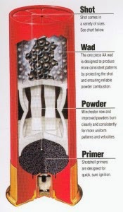
shotgun shell case cutaway If you recall, our discussion on internal ballistics focused on the characteristics of the firearm, the cartridge, and the initial actions in the firing sequence that occur within the confines of the firearm. For this discussion, we’ll start with the cartridges, known as shot shells, and their components :

Primer – similar to rifles and pistols, the shot shell primer is a small metal cup that contains an explosive mixture that, when struck by the firing pin, sends a small flame through the base to ignite the propellant.

Base – brass, steel, or aluminum, the base is a multi-function element that houses the primer, binds the hull, and provides rigidity to interact with the extractor and ejector to ensure firearm function.

Hull – polymer, plastic, or paper, the hull ensures the proper functioning of the shot shell by holding the individual components together behind a crimp. Once the propellant is ignited, the hull expands to the diameter of the chamber and ensures a sufficient gas seal to send the wad and shot forward.

Propellant – similar to rifles and pistols, the propellant, once ignited, produces the gas expansion required to fire the projectile(s).

Wad – Different from rifles and pistols, a shot shell requires a wad in order to: (1) provide a small internal compartment to contain the propellant and keep it separate from the shot or projectile; and (2) provide a buffer that absorbs shock and minimizes deformation of the shot as it accelerates from rest to initial velocity.

Shot – From a collection of very small to large lead or steel pellets through slugs, sabots, or less-than-lethal projectiles, the shot is a single or group of projectiles delivered from the firearm to the target.

Gauge and Chamber


shotgun-gauge Whereas rifles and pistols are designated by the caliber of the projectiles they fire, shotguns are designated by the shotshell gauge. While most shooters have heard the common gauges of 12, 20, 28, and .410, few know the origin of the term. A shotgun’s gauge is determined by the number of round projectiles of equal diameter that can be subdivided from one pound of lead. For example, a 12-gauge barrel was designed around the fact that one pound of lead could be divided into twelve 0.727-inch lead balls. The same methodology is true from the 4 gauge down to the 28 gauge. .410 is the exception to the rule since it was simply a determination of the diameter of the bore in fractions of an inch.

While the gauge determines the inside diameter of the bore, the chamber designation determines the maximum length of the cartridge. Most shotguns can chamber a cartridge of either 2-3/4 inches or 3 inches while others can handle a 3-1.2 inch shell. Together, the gauge and chamber determine the maximum volume of shot or size of the projectile.

Shot


Whether lead, steel, or another material, the shot is a volume of small diameter round projectiles. In the preceding section, we discussed how the gauge and chamber determine the maximum volume of shot a cartridge can contain, the diameter of the shot itself will determine how many projectiles can fill that volume. Ranging from #12 shot (at 0.05 inches per ball) to OOO, or triple-ought (at .36 inches per ball), each have their own application. Skeet shooters engaging fast-crossing targets at close range desire a large quantity of small pellets, so they typically choose a #9 shot. Conversely, trapshooters engage targets moving quickly away from the shooting position, so they choose either a #8 or a #7.5 shot with the requisite momentum to catch-up to and break the clay pigeon. The smaller shot is ideal for breaking clay pigeons or taking-down game birds without destroying their feathers or meat, but the small shot retains insufficient energy to take-down a larger game animal or subdue a felon. In these cases, the larger buckshot, slug, or sabot is chosen.

Internal/External Ballistics – Smooth-Bore, Forcing Cone, and Chokes


Break-open, pump, and semi-automatic shotguns share the same cycle of operations and functions as the rifles and pistols I covered in Internal Ballistics – Part I. Very briefly, as the firing pin strikes the primer, a small flame is sent through the base and into the hull, which ignites the propellant. The resulting rapid gas expansion pushes the plastic hull against the inside of the chamber causing a seal from which the wad and its contents can only push forward down the bore.

Shotguns, however, differ from pistols in rifles in three main areas: smooth-bore, forcing cone, and chokes. While some shotguns are manufactured with rifled bores, many more are manufactured with smooth bores. The rifled bore is designed primarily for the rifled slug and sabot rounds and produces the gyroscopic stability required to send the projectile to the intended target. Technically, birdshot and buckshot can be fired through a rifled bore, but the rifling will “spin” the plastic wad which will translate the centrifugal force to the shot and open the shot column into a “V,” leaving a large gap in the center of the shot spread. Therefore, birdshot and buckshot are meant to be fired through smooth-bores.

Since the chamber is larger than the bore, something needs to gradually “step-down” from the hull diameter to the inside diameter of the bore. This is the forcing cone. The length and shape of the forcing cone will affect the efficiency of the wad and shot traversing the length of the barrel. Too-short of a forcing cone can exert undue stress on the lead shot and cause deformation while too-long of a forcing cone may not generate enough pressure for sufficient initial velocity.

Once the wad and the shot exit the barrel, the volume of shot expands in both length and width. The size of the shot, shape of the forcing cone, and constriction provided by the choke work together and determine how much the shot column spreads as it travels down-range. As this shot column passes through a two-dimensional plane at any distance, it leaves a pattern. The following graphic demonstrates the spread of the shot pattern at different distances.... Read more

Posted by Howard Hall

Tuesday, October 7, 2014

External Ballistics Part IV – Deviation, Gyroscopic Drift and Wind Deflection

External Ballistics Part IV
Thank you for your continued interest in ballistics: the science of shooting! We have covered a lot of ground throughout this series in order to build to this last set of concepts and principles that will help you accurately and consistently place your shots on target. We will finish our discussion on External Ballistics by discussing Deviation, Gyroscopic Drift and Wind Deflection.

Deviation


The dictionary defines deviation as the difference between an expected and observed outcome or as the difference between the average outcome and a particular outcome. For our purposes, the “outcomes” are projectile impacts on target and a deviation is the difference between the point of aim and the point of impact or the difference between one particular impact and the rest of the group.

accuracy precisionI first introduced the difference between mechanical precision and shooter accuracy in Part II of our discussion on Internal Ballistics. If you recall, mechanical precision describes the capability inherent to the ammunition/firearm combination and their ability to consistently place projectiles in close proximity to one another, or in a tight group. Accuracy, on the other hand, describes the shooter’s ability to harness the mechanical precision and place a tight group focused within the intended area of the target.

While the Internal Ballistics Series focused primarily on mechanical precision and how to produce tight groups, External Ballistics has analyzed factors that affect the projectile’s flight to target. Whether it is a matter of precision or accuracy, the definition of deviation is applicable.

In regard to deviation, the most common measurement is Minute of Angle (MOA) to describe the distance between shots on target. I’d like to take a little time to discuss MOA to set the foundation for measuring deviation and better understanding Gyroscopic Drift and Wind Deflection.

Minute of Angle (MOA)


Any forces that affect a projectile’s flight become more pronounced the further the projectile travels. Stated differently, a small error will have little effect at close range, but a greater effect at a longer range. So, how do we characterize this in consistent terms? Since we are trying to measure the difference between terminal impacts from the same point of origin, this difference can be described as an arc, or more succinctly as an angle.

A full circle can be divided into 360 degrees, and each of these degrees can be divided into 60 minutes. Without taking you on too much of a tangent, this terminology came from the ancient Sumerians in the 3rd Century, B.C.. In order to track the distances or movements of celestial bodies in the night sky, they developed the sexagesimal system of measurement. Using this “base 60″ system, they subdivided each of a circle’s 360 degrees into a subdivision of 60 minutes per degree and this system is still in use today. Talk about longevity!

Many of you who have heard that 1 MOA = 1 inch at 100 yards; 2 MOA = 2 inches at 200 yards, and so on. This is MOSTLY true. Let’s take a closer look and start with calculations at 100 yards.

onemoaop

If the distance from the shooter to the target is 100 yards, then 100 yards is the Radius of a circle from which we must base our calculations. Converting 100 yards into inches, we get 3,600″. Since Diameter is 2*pi*Radius (2*3.14579*3,600), we get 22,619.462″. This is the numerator. Now, we need to define the denominator, which is 360 degrees multiplied by 60 minutes, which equals 21,600 minutes. So, to calculate the deviation of one minute of angle at 100 yards, we divide the numerator of 22,619.463″ by the denominator of 21,600, which ultimately equals 1.0472 inches. Now you know the mathematics behind calculating minute of angle and you can see that while it is not EXACTLY 1 inch at 100 yards, it is close enough for all intents and purposes.

Mount Vernon-20140927-01039Applicability: Mechanical precision is determined by the aggregate quality of the firearm components and ammunition. An “average” hunting rifle should be expected to consistently shoot within 3MOA. This equates to roughly a 3 inch group at 100 yards, 6 inch group at 200 yards, etc. More precise rifles consistently shoot between 1.5 and 1MOA whereas Precision rifles are capable of shooting “sub-MOA” groups. Aegis Academy teaches the principles of Fit, Function, and Finances when it comes to selecting a firearm. Only an individual shooter can determine if the “function” of 3MOA or sub-MOA is worth the corresponding “finances.” As a competitor and student of ballistics, I prefer rifles and home-made ammunition capable of sub-MOA precision. For example, in the photo you see a three-shot group at 100 yards. The extreme spread is just over 1/2 inch and the group size is just under 1/2 inch, so this is sub-0.5MOA. This was shot from my Remington 700, chambered in .308, with a 26″ heavy barrel using Sierra Match King 175gr Hollow Point Boat Tail bullets averaging 2,762 ft/sec initial velocity.

Let’s continue the discussion for pistol shooters. How much precision do you need with a pistol? Again, this will depend on its intended use and the shooter’s personal calculus of fit, function, and finances. Most pistol manufacturers correctly focus their manufacturing and advertising on the reliability of their products instead of intrinsic precision. So, it is difficult to gauge how “precise” most pistols are. 1911 enthusiasts recognize the name Wilson Combat as a manufacturer of high quality (and expensive) pistols. I mention Wilson Combat only because their advertising includes guarantees of precision as a specification for each pistol. For example, the Close Quarters Battle (CQB) model lists an accuracy guarantee of 1 inch at 25 yards (click here). From what we just learned… a 1 inch group at 25 yards translates roughly into 4 MOA… all for just under $3K. Wow! While that may seem alarming, consider that bulls-eye matches only shoot out to 50 yards and defensive pistol shots would probably take place within 3-5 yards. I’ve shot a lot of pistols over the last 20 years, and I don’t believe that there have been any that couldn’t maintain a semblance of a group out to 15 yards. For most pistol uses, reliable function is more important than precision.

Drift


A key theme highlighted in the External Ballistics series has been that the moment the projectile departs the bore, many forces act on that projectile and affect its travel to the target, causing varying degrees of deviation. A key take-away from this principle is that the longer the projectile is in the atmosphere traveling to the target, the more susceptible it is to external ballistic effects.

Many shooters associate the effect of wind on a projectile as drift… calling it wind drift. This is technically incorrect. I’ll attribute wind’s effect on projectiles in the section that immediately follows this one. Drift is more accurately attributed to a projectile’s side movement caused by gyroscopic spin and precession. Yes, I dug that one out again.

If you recall our discussions from External Ballistics Part I, precession is a force exerted on an object as a result of air resistance reacting to the object’s rotation and exerts this force at a 90 degree angle in relation to said force. Since the bore axis is angled “up” in relation to the sight axis, the projectile departs the bore slightly “nose up.” This creates additional air resistance under the nose of the rotating projectile. Precession causes the nose to begin to angle down in relation to the ballistic trajectory which keeps the nose of the projectile oriented on the target.

How Precession Alters A Projectile's CourseFor longer shots which keep the projectile traveling in the air for longer durations, the atmospheric resistance acting against the projectile’s rotation causes additional precession and alters the projectile’s path in the direction the projectile is spinning. This is drift! A projectile fired out of a rifle with a right-hand twist barrel will spin clockwise (to the right). The longer that projectile is in the air, the more likely precession will cause it to drift to the right… even in the absence of wind. The opposite is true for a left-hand twist barrel.

Applicability: In Internal Ballistics Part III, we covered bullet drop at different distances. Now, we see that at greater distances, we also need to compensate for gyroscopic drift. How much compensation will depend heavily on the range to target, projectile weight, ballistic coefficient, and velocity. Rifle shooters engaging targets over 500 yards need to know their barrel’s direction of twist and add the appropriate of elevation to compensate for drop as well as adjust the windage to compensate for drift. Pistol shooters do not need to be concerned with gyroscopic drift due to their projectiles’ exceptionally short periods of flight.

Wind Deflection


Wind DeflectionSince we now know that Gyroscopic Drift is caused by precession to air resistance acting against a rotating projectile, we can tackle the challenge of Wind Deflection. Even when all aspects of mechanical precision can be harnessed by proper sight alignment, sight picture, and refined shooting technique… ubiquitous wind deflection can change everything.

Assessing and correctly adjusting for wind has been my personal nemesis for as long as I’ve been shooting rifles. What makes wind deflection so difficult is that assessment and compensation must be made for both wind speed and direction. Exacerbating the problem at longer ranges is that speed and direction are not necessarily consistent and can change. I’m sure that any of you who have been on long range shoots have been confounded by seeing wind flags pointing in opposite or alternating directions along the length of the range. Which flags should you pay attention to: those closest to you where the projectile velocity is the greatest, or further down range where velocity is lower? Thinking back to our discussion on deviation, any force, including wind, will affect the projectile the most in the proximity of the shooter. Remember, any influence close to the shooter will immediately alter the projectile’s path and exacerbate the deviation down range.

Since we’ve established the wind’s profound effect on projectile travel, let’s discuss how we assess and correct for wind.

Estimating Wind VelocityEstimating Wind Velocity: Again, the wind closest to the shooter will have the greatest effect on the eventual path of the projectile. Hand-held anemometers can provide precise wind velocity readings (and even rudimentary wind direction) at the firing point. These cost anywhere from $50 – $200 depending on the additional features included. While these are “nice to have,” they are by no means necessary. Shooters have been estimating wind by evaluating range flag angles (when present) or simply observing the environment around them. According to Robert Rinker, author of Understanding Firearm Ballistics, “A wind speed of 1 or 2-mph is calm and can be disregarded. From 3-mph up to about 6 is a light breeze, noticeable but not a problem to hold a match or a paper.” The Millet Sight web page includes an article that further describes winds as follows: “Winds from 5-8 mph will agitate leaves on trees. 8-12 mph winds raise dust. 12-15 mph winds sway small trees and water begins to whitecap at 17mph.”

Estimating Wind Values


Now that we can gauge wind speed, we need to evaluate how wind direction affects projectile flight. Instead of discussing the 360 degrees of a circle, it is more effective to superimpose the image of a clock over the shooter in the very center.

Estimating Wind Values

Winds approaching from 12 or 6 o’clock (directly in front or behind) are considered “No Value” winds and require no windage adjustments. Winds from 1-2, 4-5, 7-8, and 10-11 o’clock (oblique angles) are considered “Half-Value” winds and require moderate compensation. Winds crossing perpendicular from 3 or 9 o’clock are considered “Full Value” winds and require the greatest compensation.

Correcting for Wind Deflection


OK… now that we can gauge wind speed and determine wind values by direction, we need to apply the appropriate adjustment on our rear sights or scopes. There are two things to remember here. First, we must adjust the sight/scope to move the projectile impact in the opposite direction of the wind. Second, for adjustable iron sights, we move the rear sight in the same direction that we want to move the projectile impact. If we calculate a full value wind from 9 o’clock (left to right), we want to move the impact of the projectile to the left (against the wind) and therefore, we want to move our rear sight to the left as well. Both iron sights and rifle scopes should indicate how many MOA each “click” is worth.

Although there are many methods to compensate for wind deflection, I have used the following two to varying degrees of success.

Kentucky Windage: This colloquial term best describes not necessarily adjusting the sights, but adjusting the point of aim to compensate for the wind. After each shot, I gauge the impact and further adjust the point of aim to try to score a hit. While I know a few very experienced shooters who have mastered Kentucky Windage, I am most definitely not one of those shooters and do not recommend this method as a primary marksmanship tool.

Using Wind Drift Data: Most manufacturers either provide specific wind deflection data for their load or their web site includes a ballistic calculator from which you can calculate wind deflection for your load. For my primary .308 cal load, I used the Hornady Ballistics Calculator, entered the bullet data, and calculated wind deflection for a 10 mph full value wind. See the chart below and note the text in the upper left-hand corner, recommending that you tape this “cheat sheet” to your gun.

Using Wind Drift Data - Ballistic Chart

This chart tells me that if I am engaging a target at 300 yards in a 10mph full value wind from 3 o’clock (right to left), I can expect my projectile to be deflected by the wind (even though Hornady calls it drift) 6.1 inches to the left, so I need to add 1.9 MOA of windage to the right. Since my scope is 1/4MOA per click, I need to round up to 2 MOA and apply “8 clicks” of right windage to my scope.

Well that’s great if I encounter a 10mph full value wind. What if the wind speed is, indeed 10mph, but it is coming from one of the obliques? Easy… since the obliques are considered half-value winds, the deflections and corresponding corrections are simply half of those listed on the chart. The same is true of wind speed. A 5mph full value wind would also be only half of what you see on the chart. These charts are very useful.

What about pistol shooters? Although the pistol projectile’s travel to target takes an exceptionally short time, it is not immune to the effects of wind. Again, using Hornady’s Ballistic Calculator, I entered the data for my 230gr full metal jacket .45ACP ammunition with a ballistic coefficient of .205 being fired with an initial velocity of 772 feet per second at a target 100 yards away with a 10mph full value cross wind.

Pistol Ballistics Chart

As you can see in the chart, the wind will deflect the 230gr .45ACP projectile 0.2 inches at 25 yards and 0.6 inches at 50 yards. The average adjustable rear sight on a pistol measures 1MOA per “click adjustment.” So, if I was shooting National Match Slow Fire at a 50 yard target in these conditions, I would only adjust my rear sight one click “into” the wind.

Those of you who have shot pistols in high winds would agree that the wind has a far greater effect on the shooter than the projectile.

Conclusion


We have certainly covered a lot of ground with three articles dedicated to Internal Ballistics and four dedicated to External Ballistics. If you have the time and the interest, please review or catch-up on the series in order to set the stage for our upcoming series on Terminal Ballistics where we study the transfer of energy from the projectile to the target as well as the terminal ballistic effect of those projectiles on different targets.

Please click the following titles to review past articles in the series.

Until next time, stay safe and shoot straight.

About Author

Howard Hall Range Master
Howard has served for nearly 20 years in the Marine Corps. He has served as a Platoon Commander, Company Commander, Battalion Executive Officer, Regimental Operations Officer, and Battalion Commander. He has multiple combat tours to include serving as a military transition team member in Fallujah. He is an NRA Certified handgun instructor and holds numerous Marine Corps training credentials. An active competitor in action pistol (United States Practical Shooting Association), long range rifle (NRA F-Class), and shotgun (Amateur Trapshooting Association, National Skeet Shooting Association), howard has earned numerous accolades and medaled during DoD competitions with the 1911 platform in bulls-eye shooting.
Source : Aegis Academy

Wednesday, July 16, 2014

External Ballistics Part III – Understanding Trajectory

Projectile Trajectory
Thank you for returning to our third and final discussion on External Ballistics. In this article, I will discuss the elements that affect projectile trajectory, such as sonic vs. sub-sonic velocities, ballistic curve and “zeroing” the firearm. This last article on external ballistics ties other articles in this series together in order to provide you with an understanding on how to leverage trajectory and consistently place your shots where you want them. This also establishes a solid baseline for the following articles on terminal ballistics, which describe projectile effects on impact.

Trajectory

Trajectory is simply defined as the curved path a projectile travels from point of initial velocity to impact. As we discussed in previous articles, upon exiting the firearm bore, the projectile’s initial velocity, momentum, and direction are affected by the external forces of gravity, air resistance, yaw, precession, and nutation. These external forces combine in a unique way to send the projectile along a relatively predictable path. Understanding the effects of these forces provide the shooter with the ability to combine accuracy with mechanical precision.

TrajectoryThis may be a good time to dispel a common myth. Many have described projectile trajectory as “rising” during its flight to target. Although the projectile travels in a modified parabolic arc, the myth of projectile “rise” is not true in relation to the bore axis (line from the bore to the target). The projectile initially exits the bore in a straight line. The moment gravity and air resistance act on the projectile, it is “pulled toward the earth” and the projectile follows a downward arc. Yaw, nutation, and precession guide the tip of the projectile in the direction of this downward arc which keep it oriented toward the target. Therefore the projectile never “rises” above the line of the bore axis. The line of sight and the bore axis are NOT parallel. The bore axis and the line of sight are offset to compensate for projectile trajectory. Although subtle, the line of sight is a straight line between the shooter’s dominant eye and the target… but the bore axis is tilted slightly upward to ensure the projectile trajectory terminates on the intended target. Herein lies the source of the misperception: the projectile never “rises” above the bore axis… but it most certainly rises above the line of sight.

Trajectory as a modified parabolic arcAlso, note that I’ve described projectile trajectory as a modified parabolic arc instead of a true parabolic arc. If gravity was the only external force acting on a projectile, then it would travel in a true parabolic arc. However, air resistance causes drag on the projectile and “slows it down” throughout its travel to the target. The further the projectile travels, the longer air resistance affects the projectile and thus decays the parabolic path to target and increases the bullet drop.

Sonic vs Sub-Sonic

Sonic speed“Sonic speed,” or the speed of sound in the atmosphere is of particular interest to shooters. The speed of sound is the rate at which small pressure disturbances will be propagated through the air and this propagation speed is solely a function of air pressure. The speed of sound is directly related to temperature and air density at altitude. In general terms, sonic flight is 1,125 feet per second (f/s) at 68 degrees F at sea level (767mph, or 1 mile in 5 seconds). The speed of sound increases as the temperature increases, and decreases as temperature decreases. In most cases, we can use 1,120 f/s as sonic flight for a projectile.

So why is this important to shooters? We’ve discussed how air resistance creates drag, slows projectile velocity, and decays the parabolic arc. At velocities below the speed of sound, air is considered incompressible. Therefore, air resistance simultaneously builds at the tip and along the entire surface of the projectile (laminar flow). However, at supersonic speeds (above the speed of sound) there is no build-up of air resistance at the tip of the bullet and the projectile travels with greater efficiency. Projectiles traveling above 1,120 f/s maintain greater aerodynamic efficiency. When drag eventually reduces this velocity below 1,120 f/s, aerodynamic efficiency is lost, parabolic arc decays, and trajectory drop increases.

Ballistic Curve

Now that we have solidified the fact that the projectile does not “rise” in relation to the bore axis, but it does, in fact, follow an arc from the point of origin to the striking point in relation to the line of sight, we can now confidently describe this as the ballistic curve. From the shooter’s point of view with the sights aligned to the target, the upward orientation of the bore in relation to the sights or scope sends the projectile in an arc that “rises” along an ascending branch, reaches its maximum ordinate (max ord) and then follows a downward path along the descending branch until it reaches the point of impact on the target. The constant effect of gravity combined with the varying effect of air resistance (in relation to projectile velocity) alter the path of the descending branch in relation to the ascending branch… i.e. the drop on the descending branch is more dramatic than the rise on the ascending branch. Note that high velocity rifle projectiles fired at long range can experience trans-sonic ascending branch decay as they transition from efficient supersonic aerodynamic flight to less efficient subsonic flight. Altogether, this describes the ballistic curve.

Firearm Zero

Pistol or Rifle is zeroed at a distanceA rifle or pistol is “zeroed” when the point of impact matches the point of aim. Most pistols are zeroed at 25 yards. Rifles can be zeroed at any distance in relation to the intended target. Applicability: Once a pistol or rifle is zeroed at a distance, engaging a target closer or farther than the zero can alter the point of impact in relation to the point of aim. Above, we discussed that the projectile follows a ballistic curve in relation to the line of sight. If a pistol is zeroed at 25 yards, which means that the point of impact matches the point of aim at this distance, and a target is engaged at 10 yards, the point of impact can be “higher” than the point of aim due to impact at the ascending branch of the projectile’s flight. If the same pistol engages a target at 50 yards, the point of impact can be “lower” than the point of aim due to impact at the descending branch of the projectile’s flight. Similar principles are true for rifle shooters and the difference between point of impact and point of aim are more pronounced due to the greater distance traveled, higher max ord, and greater effect of arc decay on the descending branch. In practice, shooters should know their firearm’s zero and make either sight/scope adjustments or apply the proper sighting “offset” to ensure the projectile hits the intended point of impact.

Ballistic calculatorMany online resources provide ballistic calculator software. Some of them are free and some incur a charge. In many cases, you get what you pay for. Hornady’s web site provides a free ballistic calculator which calculates basic data points that many shooters could find useful. Just as a test, I entered my AR-15 data into the calculator. Using a 69gr hollow point boat tail .223 projectile with an initial velocity of 2,700 f/s zeroed at 100yards, the Hornady ballistic calculator computed the following.

Range (yards)Velocity (fps)Energy (ft.-lb.)Trajectory (in)Come UP in MOACome UP in MilsWind Drift (in)Wind Drift in MOAWind Drift in Mils
Muzzle27001117-1.500000
1002409889000000
2002136699-4.52.20.6000
3001882542-16.75.31.5000
4001649416-38.89.32.7000
5001441318-73.814.14.1000

What this means is that at 100 yards, the projectile would impact the target at the point of aim at a velocity of 2,409 f/s. At 200 yards, it would impact 4.5 inches lower than the point of aim at a velocity of 2,136 f/s and would require a sight/scope adjustment of 2.2 minutes of angle elevation. At 500 yards, the projectile would impact the target 73.8 inches lower than the point of aim at a velocity of 1,441 (approaching trans-sonic) and would require a sight/scope adjustment of 14.1 minutes of angle elevation. NOTE: these are simply computer calculations and should be tested to verify and add to a comprehensive data book.

Using the same calculator, I entered my 1911 data using a 230gr lead round nose .45ACP projectile with a ballistic coefficient of .207 and initial velocity of 772f/s. The Hornady calculator computed the following:

Range (yards)Velocity (fps)Energy (ft.-lb.)Trajectory (in)Come UP in MOACome UP in MilsWind Drift (in)Wind Drift in MOAWind Drift in Mils
Muzzle772304-0.500000
25760295000000
50748286-3.36.21.8000
75737277-10.413.23.8000
100726269-21.620.66000

Although the table doesn’t calculate any distances closer than 25 yards, you can surmise that the point of impact would be higher than the point of aim at distances closer than 25 yards, match the point of aim at 25 yards, and fall below the point of aim by 3.3 inches at 50 yards, 10 inches at 75 yards, and 21.6 inches at 100 yards. Since this pistol has an adjustable rear sight, I can either add elevation at the rear sight or leave it zeroed at 25 yards and elevate my point of aim corresponding to the degree of total elevation required to hit the target. Both require practice!

An internet search for the term “ballistics calculator” or “ballistics software” will produce a rather extensive list of resources. Hell, there are even smartphone apps for “handy” ballistic calculations. For the example used above, Hornady’s ballistic calculator can be found at the following link: http://www.hornady.com/ballistics-resource/ballistics-calculator

Conclusion

At this point, we’ve debunked the myth of the “rising” projectile and honed our understanding of trajectory. Come back next month when we put it all together and discuss range estimation, wind deflection, ballistic slope error (shooting uphill or downhill), and defining minutes of angle. In the mean time, stay safe and shoot straight!

Howard Hall


Range Master

Howard Hall - Firearm Instructor
Howard has served for nearly 20 years in the Marine Corps. He has served as a Platoon Commander, Company Commander, Battalion Executive Officer, Regimental Operations Officer, and Battalion Commander. He has multiple combat tours to include serving as a military transition team member in Fallujah. He is an NRA Certified handgun instructor and holds numerous Marine Corps training credentials. An active competitor in action pistol (United States Practical Shooting Association), long range rifle (NRA F-Class), and shotgun (Amateur Trapshooting Association, National Skeet Shooting Association), howard has earned numerous accolades and medaled during DoD competitions with the 1911 platform in bulls-eye shooting.

First Published at Aegis Academy

Thursday, June 19, 2014

External Ballistics Part II – Flight to Target

Thank you for returning to continue our study of ballistics. In this article, I will pick-up where we left off from our previous discussion of External Ballistics and focus solely on the projectile’s flight to target. Before introducing the key concepts of kinetic energy, gyroscopic stability and ballistic coefficient, I will provide a brief review to fully set the stage.

During our discussions on Internal Ballistics, we focused on firearm function, reliability, safety and mechanical precision. The complex sequence of interactions that initiate a projectile’s movement from the cartridge case to the end of the barrel. Essentially, it helped us understand how “our” interaction with the firearm affects its function and the start of the projectile’s travel to target.

During our first discussion on External Ballistics, we focused on the principles of Newtonian Physics and the short period of projectile instability caused by Yaw, Precession and Nutation as the projectile transitions from controlled force and rotation in the bore to environmental forces (gravity and air resistance) during free rotation. As we continue this discussion on External Ballistics and analyze the factors that affect the projectile’s flight to target, we need to concede that “our” part as a shooter has ended and all of the forces acting on the projectile are out of our control.

We need to understand these external forces, however. They allow us to “back plan” by choosing the correct firearm, cartridge, aiming solution, etc. Understanding the principles in this second article on External Ballistics will not only set-up the following articles on Trajectory and Terminal Ballistics, it will allow you to make the right mental and physical preparations to consistently place the projectile on target with the desired ballistic effect.

Regardless of the shooting discipline (target shooting, competition, hunting, self-defense, etc.), the terminal ballistic effect can only be accomplished if the projectile arrives where it is intended and with sufficient energy. Target and competition shooters need to ensure their projectile retains enough velocity and stability to optimize their accuracy with the firearm’s mechanical precision. Hunters and those using a firearm for self-defense need to ensure their projectiles retain enough energy to expand and produce the desired terminal ballistic effect.

So, let’s continue with our discussion on External Ballistics.

Velocity and Kinetic Energy
I’ve grouped these two measurements together due to their interrelated nature and role they play in terminal ballistic performance.

Velocity: This is the measure of an object’s change in position relative to time… or how fast a projectile is traveling in a specific direction. Since it is a measure of position and time, velocity can be expressed in many different units of measure, such as feet per second, miles per hour, kilometers per hour, etc. The most common measure of velocity in regard to ballistics is feet per second (ft/s).
  • With the right devices and instrumentation, velocity can be measured accurately anywhere along a projectile’s trajectory from its initial velocity (or muzzle velocity), summit velocity (at the highest point in its trajectory), and striking velocity (projectile velocity as it impacts the target). Note that I used the term striking velocity instead of the more commonly used “terminal velocity.” Terminal velocity has an exact and specific meaning which describes the greatest velocity that an object can acquire by falling freely through the air.
  • Although velocity can be measured anywhere along the trajectory, it is costly andimpractical to take this measurement anywhere beyond the muzzle. Many shooters will use a chronograph placed just a few feet in front of the muzzle to measure a projectile’s initial velocity. Chronographs are rather simple devices that are made up of sensors and timing devices. As the projectile passes over the first sensor, the clock “starts” and runs until the projectile passes the last sensor which “stops” the clock. Since the sensors are placed at a known distance, the time measured between the first and last sensor calculates the velocity. Chronographs are commercially available for between $100 and $600.
  • Applicability: Measuring initial velocity is required to calculate other important ballistic factors such as kinetic energy and bullet drop. Also, since consistency and repeatability are key factors in mechanical precision, measuring initial velocity can demonstrate how consistently (or inconsistently) a specific cartridge performs in a specific firearm.
Kinetic Energy: All objects in motion have kinetic energy. Newton’s fundamental law of Conservation of Energy states that energy can neither be created nor destroyed. Since all objects in motion possess kinetic energy, this energy must be transferred from the projectile into the target on impact. By measuring the kinetic energy of a projectile at the muzzle, we can calculate how much energy will be transferred into the target at a certain distance.
  • Kinetic energy is simply calculated by multiplying ½ times the mass of the projectile times the square of the velocity… or KE = ½ * MV2.
  • While projectile velocity is typically measured in feet per second (ft/sec), Kinetic Energy is typically measured in foot-pounds. For those interested in calculating kinetic energy for themselves, KE = ((projectile weight in grains)*(velocity in feet per second)2)/(450,400). The number 450,400 combines the conversion from grains to pounds with the ½ required to calculate kinetic energy.
  • For example, I recently chronographed a few of my hand-loads in my rifles and pistols. In my Remington 700 in .308cal, I fired a series of 175 grain hollow point boat tail projectiles and calculated an average muzzle velocity of 2,762.4 ft/s. Using the formula for kinetic energy above, KE = ((175)*(2762.4)2)/(450,400) = 2,964.92 ft/lbs of kinetic energy.I conducted the same test with my AR-15 in .223 and my 1911 in .45ACP. In the AR-15, the 62gr projectiles averaged 3,036.80 ft/s and resulted in 1,269.48 ft/lbs of energy. In the 1911, the 230gr projectiles averaged 772 ft/s and resulted in 304.34 ft/lbs of energy.
  • The important concept here is that velocity plays a greater role than projectile weight when it comes to kinetic energy. Notice how the .45cal bullet is clearly the largest projectile fired in my test, but its low velocity resulted in the lowest kinetic energy. Also note how the weight of the .223 projectile was just over one-third the weight of the .308 round, but due to the fact that it was nearly 300 feet-per-second faster than the .308 round, it possessed just under one-half of the kinetic energy at the muzzle.
  • For a very loose comparison, scientists have “estimated” that a professional boxer’s punch delivers 330 ft/lbs of kinetic energy. (note, this is a very rough estimate because the boxer’s fist is attached to the body which is not “limp” on impact. A boxer can continue to “thrust” a punch following impact whereas a firearm projectile is left with only resultant mass and velocity). For the purposes of this argument, compare the 330 ft/lbs of a boxer’s punch to the muzzle energy of the 175gr .308 (2,762.4 ft/lbs), 62gr .223 (1,269.48 ft/lbs), and 230gr .45ACP (304.34 ft/lbs).
  • Applicability: Even with the considerable kinetic energy of the 175gr .308 projectile, there is really no such thing as “knock-down power” in regard to human or large animal targets. Granted the projectile’s kinetic energy will puncture paper or knock-down certain steel or wooden targets that are designed to fall, the energy transferred from a projectile into a human or large animal target will not knock it down from impact alone. The kinetic energy transferred will, however, contribute to penetration and/or expansion. Therefore projectile performance and shot placement play the greatest role in ending the threat or taking down the game animal. This will be discussed in greater detail in my forthcoming articles on Terminal Ballistics.
Gyroscopic Stability

If you recall our discussion in External Ballistics Part I, there is a moment when the projectile transitions from controlled movement in the barrel to free-rotating travel outside of the barrel when Yaw, Precession, and Nutation cause it to “wobble” in a helical pattern.  You may also recall how these forces quickly dampen the “wobble” into a predictable and stable flight.  This is due to the fact that All spinning objects possess gyroscopic properties.  In a firearm projectile, these gyroscopic properties contribute to a principle called “rigidity in space” which creates the gyroscopic inertia required for the projectile to travel along a predictable trajectory.
  • In general, a heavier projectile is more resistant to disturbing forces than a light mass… i.e. heavier projectiles maintain a greater gyroscopic stability and are less affected by wind, and incidental contact than lighter projectiles.
  • The higher the rotational speed (i.e. faster rifling twist), the greater the rigidity, gyroscopic inertia, and resistance to deflection (wind).
  • Applicability: in theory, a heavier projectile with a higher rotational speed will maintain its gyroscopic stability better than a lighter projectile with a lower rotational speed.
Ballistic Coefficient

As we covered in External Ballistics Part I, gravity and air resistance immediately exert force on a projectile the moment it leaves the barrel. So far in this article, we’ve covered muzzle velocity, kinetic energy, and gyroscopic stability en route to understanding our goal - how to ensure a projectile retains as much muzzle velocity as possible for both predictable ballistic flight and to ensure effective terminal ballistic performance. This leads us to the term Ballistic Coefficient, which is a measure of how well a projectile can overcome air resistance and maintain flight velocity. Mathematically calculating the characteristics of projectile weight, diameter, and shape, the ballistic coefficient measures the projectile’s ability to conquer air resistance. This mathematical equation produces a number between zero and one. The higher (closer to one) ballistic coefficient is preferable as this indicates it will maintain its velocity better than a projectile with a lower ballistic coefficient (closer to zero).
  • Shape - the third factor in determining ballistic coefficient is the shape from theprojectile tip through the ogive to the surface area of maximum diameter combined with the shape of the base. In general terms blunt tips with flat bases have the least efficient form factors whereas sharp tips with long ogives and boat-tails have the most efficient form factors.
  • Weight and diameter - These two measurements combine to determine sectional density of a projectile. Sectional density is measured by dividing the weight by the square of the diameter. SD=w/d2. Heavier projectiles possess greater gyroscopic stability and resistance to wind. Large diameters, however, incur greater air resistance. Therefore, the most proficient projectiles are those that are the heaviest in proportion to their diameter (caliber).
  • Applicability: the most common way to design a heavier projectile of the same caliber is to make it longer.
  • Applicability: A projectile with a high ballistic coefficient will travel to the target with a flatter trajectory, will spend less time in flight, and be less influenced by air resistance and wind deflection… therefore, it will arrive at the target with the greatest amount of residual velocity and kinetic energy.
Wow, that was quite a ride. Just remember: measuring muzzle velocity allows you to determine the consistency of your cartridge selection and calculate bullet drop and kinetic energy; velocity has a greater effect on kinetic energy than projectile weight; heavier projectiles with a higher rotational velocity are more stable and less affected by wind; long, heavy, and sleek projectiles with boat tail bases travel along a flatter trajectory, spend less time in flight, and arrive at the target with the greatest amount of residual velocity and kinetic energy.
With all of this knowledge in hand, we will be ready to discuss bullet drop, wind drift, and trajectory calculations in the next article. Until then, stay safe and shoot straight!

About Author


- Howard Hall 

Range Master

Howard Hall
Howard has served for nearly 20 years in the Marine Corps. He has served as a Platoon Commander, Company Commander, Battalion Executive Officer, Regimental Operations Officer, and Battalion Commander. He has multiple combat tours to include serving as a military transition team member in Fallujah. He is an NRA Certified handgun instructor and holds numerous Marine Corps training credentials.  An active competitor in action pistol (United States Practical Shooting Association), long range rifle (NRA F-Class), and shotgun (Amateur Trapshooting Association, National Skeet Shooting Association), howard has earned numerous accolades and medaled during DoD competitions with the 1911 platform in bulls-eye shooting.

Source: http://aegisacademy.com/community/external-ballistics-part-ii/

Monday, May 26, 2014

External Ballistics Part I – Physics, Projectiles and Transitional Ballistics

External Ballistics Part I – Physics, Projectiles and Transitional BallisticsWelcome back to our study of ballistics. Now that we’ve covered the many aspects of internal ballistics and how ammunition interacts with the inner workings of firearm components to produce mechanical accuracy, we will discuss external ballistics. Since there are so many forces that affect a projectile’s flight from the muzzle to the target, I’ve broken the subject material down into a two part series. In this article, I will introduce some basic physics principles, discuss projectile characteristics and focus on transitional ballistics.

“Painless” Physics

First Physics Law Of CartoonsIn order to fully explain some concepts related to external ballistics, I need to briefly review the principles on which all ballistics rest: Newtonian Physics. While many of us learned our first physics lessons from Wylie E. Coyote, nearly everything depicted was incorrect. Even though we cannot observe the forces acting on a projectile the moment it leaves the muzzle, we know those forces significantly affect its actual path. In order to set the record straight, I will cover Newton’s three laws to help us better understand ballistics. Now, on to the physics.

Newton’s First Law: “A body at rest tends to remain at rest, and a body in motion tends to remain in motion at the same speed and in the same direction unless acted upon by a force.” Applicability: If it wasn’t for the force of gravity or air resistance, a projectile would travel endlessly in a straight line from the barrel.

Newton’s Second Law: “When a body is acted upon by a constant force, the resulting acceleration is inversely proportional to the mass of the body and is directly proportional to the applied force.” Applicability: Force = Mass X Acceleration. For this discussion of ballistics, the projectile’s mass is constant, so force and acceleration are directly proportional. Therefore, a change in acceleration results in an equal change in force.

Newton’s Third Law: “Whenever one body exerts a force on another, the second body always exerts on the first a force which is equal in measure, but opposite in direction.” Applicability: For every action there is an equal and opposite reaction as can be seen in felt recoil, pressure build-up from air resistance and terminal impact.

Why is this important to ballistics? All three laws act together to describe the interaction of forces that affect a projectile’s flight to target. At the moment the primer ignites the propellant and rapid gas expansion thrusts the projectile forward, the projectile experiences dramatic acceleration. The third law describes how the force required to propel the mass results in an equal and opposite force we know as felt recoil. The very moment the projectile leaves the barrel, friction from air resistance combines with gravity to simultaneously decelerate the projectile and alter its path in a modified parabolic arc (trajectory) toward the earth. As the projectile impacts the target, it decelerates from its residual terminal velocity to zero with an energy transfer that is equal to one-half of the projectile mass multiplied by velocity squared to produce a ballistic effect (third law). But there is more…

Projectile Nomenclature

Projectile design significantly affects performance from ignition, travel through the bore, trajectory, and target impact. While there are many variables, I will briefly describe the characteristics common to most.

Meplat/Tip: If the tip of the projectile is flat, the flat surface is called a Meplat. Otherwise, it is called the tip, nose or point. This leading edge affects the amount of drag (air resistance).
Bullet Parts
Ogive: This is the gradual radial reduction from the shoulder to the meplat or tip.

Shoulder: This is the transition point from the bearing surface to the Ogive.

Bearing Surface: This is the somewhat longer surface area along the length of the projectile that presses against the inside of the bore. The outside diameter of the bearing surface equals the caliber of the projectile.

Cannelure: As mentioned in Internal Ballistics Part III, the projectile is secured within the case by friction as the result of a process called crimping. Some rifle and pistol projectiles have a cannelure somewhere along the bearing surface. The cannelure is a set of tooling marks or series of indentations designed to better secure the crimp and prevent projectile set-back.

Heel/Base: Ranging from flat base through boattail (tapered), the shape greatly affects the amount of drag exerted on the projectile during its flight. Base drag is caused by the partial vacuum that occurs behind the projectile during its flight. A tapered, or boattail base reduces this drag. However, studies indicate that the benefits of a boattail are negligible under 200 yards. Therefore, handgun cartridges and short-range rifle cartridges do not benefit from a boattail projectile.

Transitional Ballistics:


OK, now it is time for the heavy physics stuff. If you recall from our discussion on mechanical precision, barrel rifling will rotate a projectile along its center of mass and the barrel crown exerts the very last influence on the projectile as it exits the bore. In a perfect world, which doesn’t exist, the a perfectly concentric projectile with its uniform density dispersed evenly along its longitudinal center of mass travels down a perfectly aligned bore. It is provided the last bit of thrust with a perfectly machined crown as it enters a vacuum (no air resistance) and travels along a mathematically perfect parabolic arc. This process occurs so rapidly that most shooters would believe that a projectile exits the bore in a straight line toward the target. Again, Wylie E. Coyote’s version of physics does not apply. There is a brief period of instability as the projectile exits the barrel before all of physics principles align and stabilize the projectile. This period is called Transitional Ballistics.

Transitional Ballistics, Yaw, Precession and NutationTransitional Ballistics, Yaw, Precession and Nutation: Simply defined, Yaw is a deviation of a forward moving aerodynamic object from its longitudinal axis. Precession is an angular force applied to a rotating object caused by its torque. Nutation, literally “nodding,” is the opposing force in a rotating object that gradually “normalizes” along the longitudinal axis during projectile flight.


How air resistance opposes downward motion of projectile's noseWow! So what does that all mean? During the
projectile’s travel down the bore, the rotational acceleration is controlled solely by friction applied by the rifling. As the projectile exits the muzzle, its rotational momentum will cause it to continue to rotate in the same direction as it moves under forward momentum. Keep in mind, however, that the bore axis of a firearm is tilted slightly upward in relation to the line of sight. Therefore, although the firearm appears level, the projectile exits the bore at a slight upward angle. The very moment the projectile is free of the bore, atmospheric resistance exerts pressure simultaneously against the nose and under the ogive of the projectile at the same time. These pressures combined with any imperfections in the barrel crown cause the projectile to yaw away from its center axis. Concurrently, air resistance across the full surface area of the rotating projectile exerts an angular force at 90 degrees in relation to the direction of rotation and the orientation of the longitudinal axis, which is precession. At the same time, the projectile’s release from controlled rotation in the rifling to “free flight” outside of the bore requires a short time for the rotational inertia to stabilize along the longitudinal axis. In this process, the nose of the projectile varies in a helical motion until it is dampened to stabilized ballistic flight, which is nutation.

CG Bullet FlyingOK… let’s try it again in plain English: There is a brief moment when a projectile leaves the barrel in which it is somewhat unstable. This instability is caused by a combination of the projectile’s rapid transition from controlled rotation to free rotation and the introduction of air resistance. During this period, the projectile “wobbles” in a helical pattern as it moves forward before it fully stabilizes. You can also see this in slow-motion replays of long football passes. When the football leaves the quarterback’s hand, it is rotating along its longitudinal axis, but is wobbling for a short distance before it stabilizes into and travels to the receiver (or not). The same is true for a projectile!

Pistol ProjectilesHow does this affect the average shooter? Pistol shooters should know that these principles exist, but have little to be concerned with. The short length of pistol projectiles allow them to stabilize quickly and within just a few feet. Rifle shooters, on the other hand, fire longer projectiles that require up to 48 feet to stabilize. Matching the projectile shape and weight to the propellant charge and barrel rifling will minimize (but not eliminate) the intrinsic instability of the projectile as it leaves the muzzle. This will allow it to stabilize more quickly and efficiently allowing it to travel with greater precision and energy conservation to the target.

The bottom line is there are a lot of forces that simultaneously act on a projectile the moment it leaves the barrel and it takes a short time for the projectile to stabilize into predictable ballistic flight. Now that we’ve covered these details, we are set up to discuss how gravity, ballistic coefficient, wind and other atmospheric effects alter a projectile’s flight to target. Check back with us to continue the discussion with External Ballistics Part II.

Until then, stay safe and shoot straight!

First Published at Aegis Academy

About Author


-Howard Hall


Range Master


Howard Hall
Howard has served for nearly 20 years in the Marine Corps. He has served as a Platoon Commander, Company Commander, Battalion Executive Officer, Regimental Operations Officer, and Battalion Commander. He has multiple combat tours to include serving as a military transition team member in Fallujah. He is an NRA Certified handgun instructor and holds numerous Marine Corps training credentials. An active competitor in action pistol (United States Practical Shooting Association), long range rifle (NRA F-Class), and shotgun (Amateur Trapshooting Association, National Skeet Shooting Association), howard has earned numerous accolades and medaled during DoD competitions with the 1911 platform in bulls-eye shooting.